CHALLENGE
A customer has been receiving field failures and the root cause has been difficult to determine. They have ideas of what may be causing these failures and need a test system that can simulate the various conditions and monitor the Device Under Test (DUT) to assist in determining the root cause. The customer turned to DISTek to provide a bench-top setup that will control the DUT and measure multiple in-circuit test points for events that may be damaging field effect transistors (FET) along with recording FET case temperatures. Custom events have been defined by the customer and will trigger the system to capture pre and post-trigger data. The test system should also provide various loads to the output of the DUT.
SOLUTION
The engineers at DISTek set out to create a flexible hardware and software test system that could be configured and expanded by the customer for the implementation of various scenarios. The solution consists of a clam-shell bed-of-nails test fixture, National Instruments (NI) measurement hardware and NI LabVIEW software.
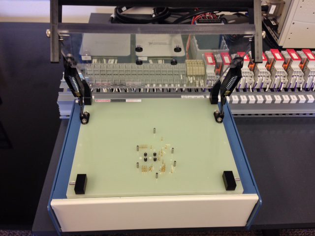
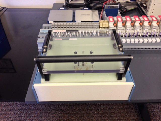
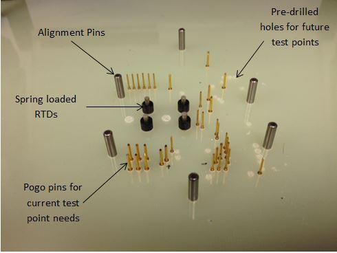
We worked with Automatiq Measurement Systems to develop a clam-shell bed-of-nails test fixture. The test fixture (Figures 1 – 3) was provided to us ready-to-wire with drilled holes, pogo pins and sockets, guide pins for alignment, custom spring-loaded resistance temperature detector (RTD) fixtures, and push down pins. The fixture was designed using the board Gerber files, test point list, and sample DUT. The benefits of this fixture are rapid & reliable loading, long connection life, low cost and quick turnaround.
The measurement system consists of the following NI hardware (Figure 4):
- NI PXIe-1071 4-Slot 3U PXI Express Chassis
- NI PXIe-8101 2.0 GHz Intel Celeron 575 Embedded Controller
- NI PXIe-6368 Simultaneous X Series Data Acquisition
- NI cDAQ-9174 CompactDAQ 4-Slot USB Chassis
- NI 9217 PT100 RTD Analog Input, 100 S/s/ch, 4 Ch module

The NI PXIe-6368 provides the output needed to control the DUT, while measuring 16 analog inputs simultaneously at 1 MHz. The 16 analog inputs are connected to the in-circuit test points via NI breakout boxes and pogo pins on the clam-shell bed-of-nails test fixture. The PXIe-6368 also provides the digital outputs to control eight relays that allow the user to connect various loads to the DUT. The NI 9217 measures the four RTDs connected to the FET cases. Both of these cards are connected to, and controlled by, the custom software and NI PXIe-8101 Controller.
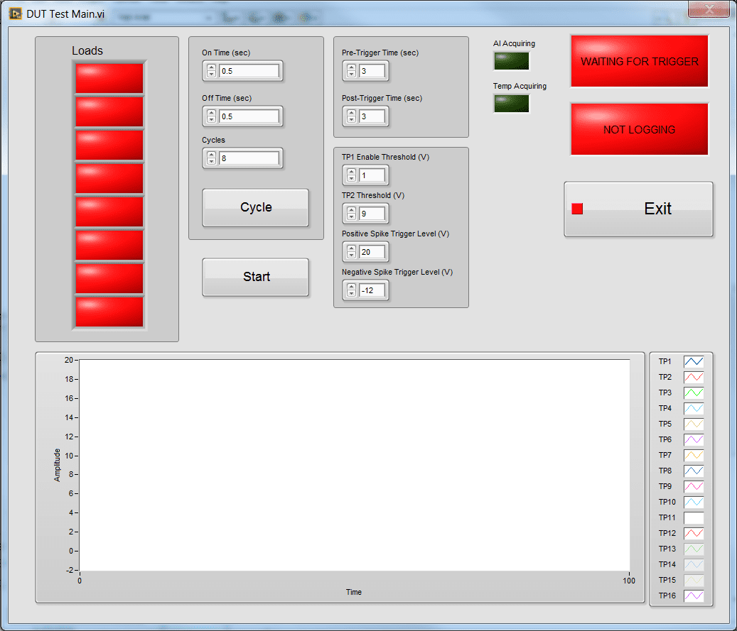
The custom software was developed by DISTek and used NI LabVIEW to control the DUT while monitoring 16 in-circuit test points and four channels of temperature. The user interface (Figure 5) is used to configure the test, start and stop testing, and monitor test point activity. The software records 6 seconds (3 pre-trigger and 3 post-trigger) when a custom trigger defined by the customer has occurred. The system continues testing after some trigger events, but will also stop testing and shut the system down on other event types.
RESULTS
This test system satisfied the customer requirements and they have been able to successfully create failures and collect the data needed to assist in determining the root cause of the field failures. This information will be used to improve the product for their customers, improve reliability and customer experience, and reduce field returns.
To view more DISTek case studies, click here.