In my work, I build Hardware-In-The-Loop (HIL) test benches. We connect prototype vehicle Electronic Control Units (ECUs) and their software to the HILs. The HILs replicate the various electronic actuators controlled and monitored by ECUs when they are connected to vehicles. We try to use the actual devices that would be used on the equipment, but there are a myriad of different reasons why this is not feasible for testing. A lot of the devices would take up too much space on the HIL. Some can be rather noisy when operating and others require complicated cooling systems to operate for extended periods of time. That is why I often create electronic circuits that will simulate the current feedback characteristics of the actuators.
Recently, I was asked to create an electrical load that would match a valve that is used to regulate the flow of fluid on an engine. Most of the time an ECU can be tricked into thinking it’s controlling a valve by simply connecting it to a coil with a series resistor. However, this particular valve is different. As the ECU supplies voltage to the valve and it begins to open, there is a noticeable “blip” in the current feedback pattern when the valve reaches a specific position in its stroke (see Figure A). The ECU constantly monitors the current going through the valve and the control system confirms the presence of the “blip” to verify that the valve has opened successfully. If it doesn’t detect the “blip”, it assumes that the valve failed to open, which then generates a fault code and warns the operator that there is a problem with the system.

Unfortunately, a single coil will not reproduce this “blip” in the wave pattern. Installing the actual device on the HIL is not an option, as the valve produces a lot of heat and can fail when operated without fluid flowing through it. I needed a more complicated circuit that would allow me to control the current flowing through the load over a period of time and change the resistance of the load at the moment in time that the valve normally pops open.
After some investigation, I came up with a solution. The basic circuit consists of two different coil and resistor loads in parallel with each other (see Figure B). The circuits are run through high-current MOSFETs, which act as relays to connect or disconnect the loads at various points in time. A separate control circuit is than used to monitor when the voltage from the ECU first goes high which starts a timer. Current begins to flow through the first part of the load circuit. When the timer reaches the point at which the “blip” would begin, the voltage to the gate of the first MOSFET is than reduced, which has the effect of reducing the maximum current that can flow through that part of the load. Once the timer reaches what would normally be the end of the “blip”, the first MOSFET goes back to passing maximum current and the second MOSFET is powered as well. This allows current to flow through the parallel loads which ramps up the overall current at a faster rate.

The load is a simple enough circuit, but I needed to figure out how to control it. I would need a control circuit with an analog input to read the voltage and start the timer. It would also need two analog outputs to control the MOSFETs. Oh, and I forgot to mention that it would need to perform the control very quickly. The valve opens in less than 6 milliseconds and the “blip” only occurs for around 200 microseconds!
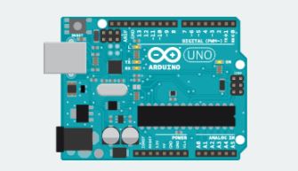
A circuit that complex would be difficult to create from scratch and I didn’t want to use the HILs expensive computer cards, as that would require me to run more wires to the load box. That’s when I found the Arduino DUE card. It’s an affordable, easy to use, standalone circuit board that uses the Atmel SAM3X8E ARM Cortex-M3 CPU to control up to 54 digital I/O pins, 12 analog inputs, and 2 DAC outputs. It is powered by 12 volts and has an 84 MHz CPU clock that is more than fast enough to switch the valve circuit’s MOSFETs. All that for under $50 retail. The best part is that it is open source and used by hobbyists all over the globe.
Basic programming is straightforward and can be done using Arduino’s free programming software via a standard, micro-USB cable. I did run into issues since the base level commands were too slow for my needs, but there is an online forum with a searchable database and it didn’t take long for me to learn how to setup the CPU so that all the control logic takes place in 1 microsecond. The timing of the circuit can be changed by sending serial messages to the Arduino that sets the points in time where the “blip” begins and ends. This is a flexible solution to change the circuit waveform for testing the ECU’s fault response logic.
The last step was figuring out how to connect the loads to the DUE card. Fortunately, Arduino also offers several solutions for connecting circuits to the board. I was able to purchase prototyping boards that plug in directly to the DUE. I built and installed custom circuit boards that contain the MOSFETs, some circuit protection, and terminal blocks for connecting the coils and power resistors.
All along the way, I was able to find all the answers I needed on the Arduino web site and in the forums. If you need an affordable, custom circuit controlled by a stand-alone CPU, I recommend checking out the Arduino website. I was able to find a solution for my needs and had fun in the process.